According to Gregor Strekelj, product manager at Allplan’s competence centre for infrastructure, BIM is no longer just for buildings, it is becoming more widely used for infrastructure as well. However, bridges come in many types and shapes, and are built with different methods, such as precast girder bridges
Precast girder bridges require a different approach to modelling, as their geometry is only indirectly governed by the axis.
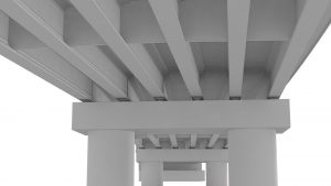
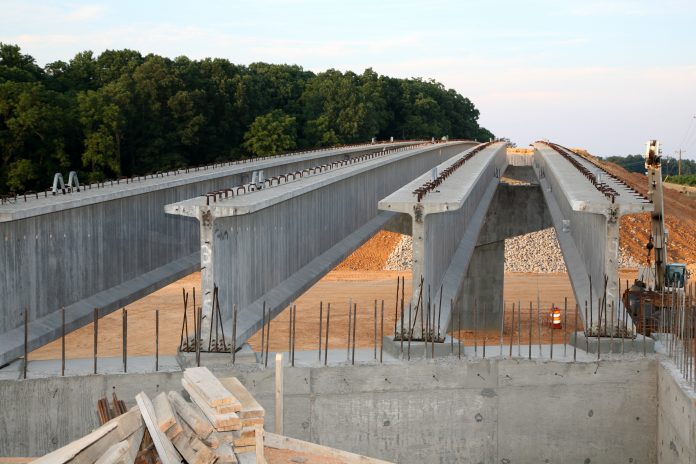
While there are different types of precast girder bridges, they all have one thing in common – their component geometry. Girders are normally straight, which is why their geometry is not directly impacted by the road or bridge axis. This is also the case with respect to their final position on the bridge, which is dictated by the geometry of the supporting substructure.
Allplan Bridge – a complete, integrated BIM solution for bridges – has been recently updated to address this need with new features that provide an updated modelling workflow so precast girder bridges can be created with ease. With just one bridge model, an entire BIM-supported bridge design process can be carried out from within this parametric design solution.
New modelling approach
Firstly, a bridge axes needs to be created or imported, and the cross-sectional geometry either designed or taken from a template. Then the substructure – with or without foundations – can be generated and the precast girders positioned on top.
Then for easy yet precise modelling of precast girders, a new element called Link Girder has been introduced into Allplan Bridge. This is a parametric, linear, 3D element between two 3D points. These two reference points define the virtual and local axis which is used for the calculation of geometry. Once this is set, it can be used for modelling tendons, defining the construction sequence and even detailing, rebar modelling and drawing production. Because it is parametric, it can be adjusted quickly and easily if there are any changes.

In precast girder bridges, girder shapes and lengths are often repeated and to address this efficiently, a new approach called modular modelling has been introduced. With this, as many templates as necessary can be generated, either for link girder elements or pier elements. Once a template is generated, it can be used in the 3D model as required simply by dragging and dropping it in. This way, all the girders can be generated rapidly, saving considerable time.
Of course, the girder shape can be another hurdle. Either the girder section can vary along the length, the exact length of the girder may vary, or the substructure may be skewed, making it difficult to model the geometry precisely. Allplan Bridge makes this easy to overcome by allowing the template length to be specified as the girder length or by using a virtual length for the template length until the girder is positioned on the substructure. Which solution to use depends on the bridge geometry and which is more convenient.
Furthermore, new station types are introduced – fixed stations – which enable fixing of the position where the girder section changes. This allows adjustment of the final girder length, and the fixed stations will remain in their specified positions. This significantly shortens the time required for modelling these types of girders.
Closing the gap between the girders and plate
The next step in the modelling process is to create a bridge deck by extruding a cross-section along the bridge axis. At this point, two bridge elements will have been generated – leaving a gap between the girders and plate. This gap is filled with what we know under the name of a haunch or fillet, but the 3D geometry of it is influenced by many constraints. The geometry of the deck slab and girder arrangement affect the haunch geometry, and the thickness may vary along the bridge axis. The construction process and vertical deflections of the girders also influence the haunch shape.
Allplan Bridge solves this problem by using 3D Boolean operations to create the haunch quickly and easily. All the parameters which govern the geometry are already defined. Therefore, the haunch just needs to be predefined in such a way that it intersects the deck plate and can be merged with it. To do this, a cross-section of the haunch is created and then the software automatically calculates and generates the final 3D form based on the other already defined bridge parameters.
With the main bridge elements modelled, other details – such as diaphragms, bearings, pavements, barriers and more – can be easily created. They can be either modelled from scratch, inserted from a library or created using customised intelligent objects.
Accelerating design processes
With this new modelling approach for precast girder bridges, together with enhanced tools for optimised BIM workflows, Allplan Bridge lets engineers focus on what they do best: designing and building safe and attractive bridges.
These new features result in an improved modelling approach specifically tailored for prefabricated girder bridges. The straightforward procedure accelerates the design process while enabling a precise model to be generated with ease. As prefabricated girder bridges are one of the most common bridge types used globally, the time – and therefore cost – savings can be significant.
To learn more about modeling precast girder bridges, watch here: Precast Girder Bridge Workflow
ALLPLAN GmbH
*Please note: This is a commercial profile


