How many buildings are suffering from inefficient performance and unnecessary costs because they rely on design preconceptions rather than actually analysing how key systems and building services work? Carl Collins of CIBSE and MagiCAD’s Rob Harmer examine what’s going wrong
Design preconceptions that are commonly used in place of actually analysing systems properly cause a lot of wasted effort and site reworking, adding cost to projects.
Carl Collins – Digital Engineering Consultant, CIBSE
For as long as I can remember, I have been designing buildings and systems based on the received wisdom of those that came before us. As design time has been eroded away over the years, to keep a cap on costs and keep profitability up, I have had less and less time to really look at what I have been designing and the basic concepts and assumptions upon which those designs hang.
But what if our predecessors were wrong? What if the assumptions I have always taken as read were, in fact, based on an incomplete understanding of how buildings work? The physics of building designs has progressed a long way in the last few decades, have our assumptions caught up? Has the experience of people on-site been fed back to close the assumption loop? Nope.
To demonstrate this rather outrageous statement, let’s take a look at one particular design flow that mechanical building services engineers will be all-too familiar with: designing ductwork systems. This is not to cast the mechanical engineers as the bad guys; this can be extrapolated to any discipline or any workflow. We are just writing about what we know.
Take a typical ductwork system. You push air in at one end and it comes out of a ceiling-mounted diffuser at the other. Obviously, at one end the pressure will be greater than at the other, so we need to control the air flow using dampers of some description to even it all out or all the air will come whistling out of the first diffuser and nothing will come out of the last.
What we generally do is to make an assumption about where most of that control will need to be done and put our control devices in that air stream to throttle it back, so the other diffusers can get some air too. The path of most resistance is then referred to as the “Index Run”, which, if the fan that is pushing the air is correctly specified, will not need any control, as this is the maximum effort of the system. In reality, some control is usually put in here, but in an ideal world it would be fully open. What we designers do not really do is assess the ease or even possibility of commissioning the system before it reaches site, so we just place VCDs on branches where we feel it seems right and leave it to the site commissioning engineers to sort out. In fact, this means that huge pressure fluctuations and noise could result, which is in fact an ‘unbalanced’ system.
The Index Run has usually been assumed to be the ductwork that goes to the diffuser farthest away from the fan. That was what I was taught and, to my shame, I never questioned it as it seemed obvious. But now we have digital methods of fully interrogating and simulating what would really be going on and it came as quite a surprise to me, although now I think about it, it shouldn’t have (I’m supposed to understand physics!), that it was more complicated than that. I’ll hand you over to Rob to explain how we analyse and solve this issue with digital tools.

Rob Harmer – Technical Area Manager, MagiCAD
As Carl described, ductwork (and pipework) system design has many traditional and unquestioned assumptions – but we can use digital engineering methods to represent real-life situations and run simulations on these to assess whether they are suitable or not.
One such means to accomplish this is to use the flow and pressure analysis of our MagiCAD software within the Revit software platform. Other solutions are available; we are using our software as it is what we know best and illustrates the issue. In short, it allows the user to model and connect system components to represent the geometric ductwork distribution and terminals etc, but then run simulations to see what would actually happen in this system in real life. It is not enough just to run a traditional calculation to find the highest pressure drop due to ducts and fittings, add on a bit more for components, and then size a fan (or pump if talking about piping systems).
What we can do, with clever use of variable VCDs, air terminals with dampers and applying variable sizing methods, is to create a ‘balanced’ system where all pressure fluctuations are dealt with properly. For example, pushing 500Pa off a fan and then immediately branching directly off this main duct on to a grille may look fine on a drawing and the index run calculation would be absolutely fine, but this system would be way off being balanced in reality.
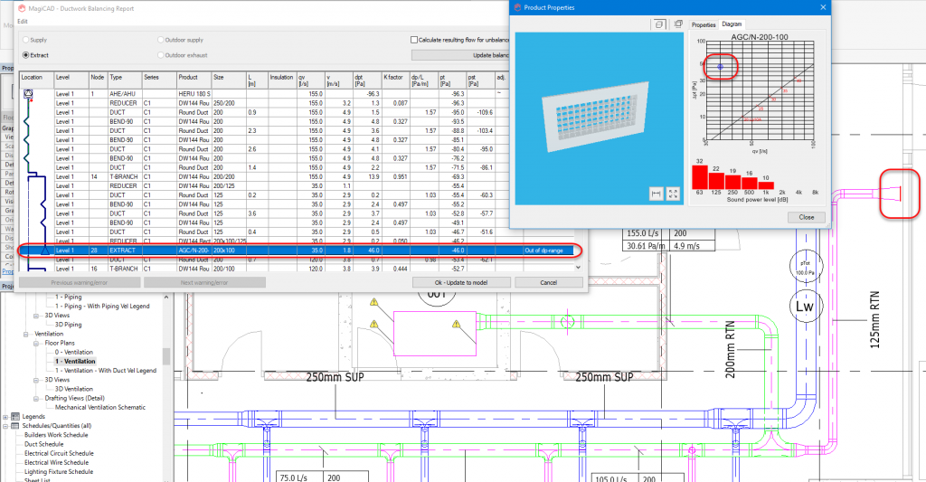
The above image shows an example of this. There’s a grille mounted to the end of the duct, which turns out not to be the index run. This should be balanced, but you can see that actually, the pressure drop would need to be 46Pa to handle this increased pressure, which exists to serve the index run conditions. In reality, what would happen is that a flow rate far higher than the design rate would pour through here, thus starving other grilles. MagiCAD calculations report this anomaly with a warning in the report for the user to check. On site it is too late to realise this at the commissioning stage.
 When using MagiCAD’s flow analysis for this situation, it now reports the reality, whereby the flow would be 52.2 l/s rather than 35 l/s. As a result, this system is uncommissionable.
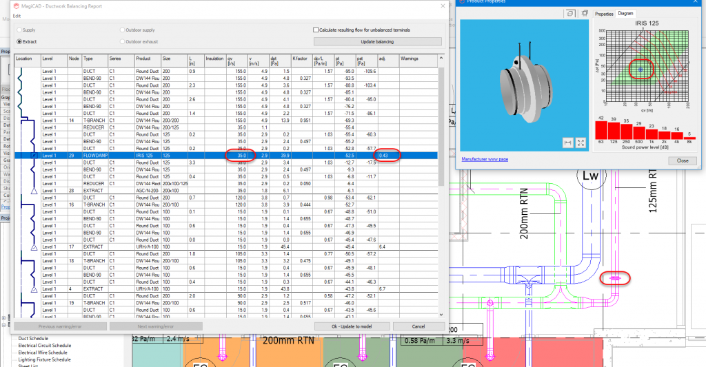
When we add a VCD into this one branch, the whole system is now balanced. Not only have we proved pre-commissioning balancing, but also challenged the assumption that VCDs are required everywhere there are branches and thus we have saved many surplus and unnecessary VCDs and their associated costs and maintenance. We have simply used the balancing tweaking of the grille itself to achieve this. The image shows the VCD in the system now regulating that flow and the technical diagram shows its performance range and even its adjustment value.
The same logic can also be applied to heating, cooling and, to an extent, domestic water systems. I wonder how many other design and engineering processes we just take as read, but can now analyse fully?
Carl Collins
Digital Engineering Consultant
CIBSE
Tel: +44 (0)20 8675 5211
Twitter: @CIBSE
Rob Harmer
Technical Area Manager
MagiCAD
Twitter: @magicad
Facebook: MagiCADsoftware
Youtube: MagiCAD & MagiCloud


