Martin Young, of Cassidy Forsythe explains why 3D modelling Rackheath bridge was a vital part of the project, highlighting problems prior to construction
As a result of 3D modelling it became apparent that the reinforced concrete could not be constructed as designed by the client.
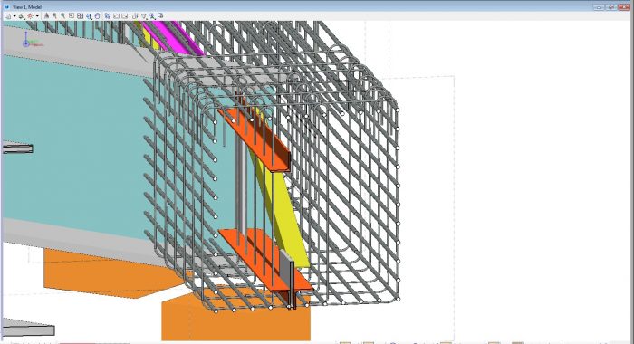
The problems found were as follows:
- Due to the length of the longitudinal bars it would be extremely difficult to install them between steel beams already installed
- Closed links would be impossible to install due to the intermediate bracing between the beams
- Stirrup reinforcement clashed with the intermediate bracing
3D modelling avoids expensive mistakes
These problems only became apparent once the 3D model had been created and hence avoided costly delays.
The solutions Martin Young suggested to the client were as follows:
- Change the longitudinal reinforcement bars so that the bars could be installed on the ground before the steel beams are lifted into place
- Change the closed links to open U bars so that they could be fixed after the intermediate bracing
- Move the stirrup reinforcement or move the intermediate bracing away from the reinforced concrete beam
These proposed changes would allow the majority of the reinforcement to be installed on the ground, reducing the inherent risk of installing reinforcement at height, during a rail possession at night.
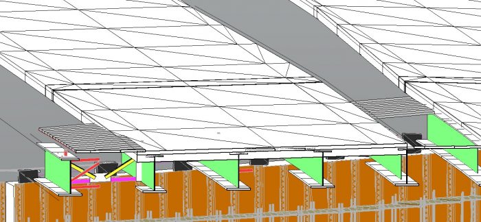
The problems highlighted by the 3D model can be seen from the screenshots below:
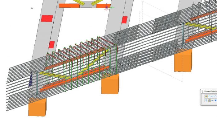
If Balfour Beatty had attempted to construct the bridge without the 3D modelling it would have been impossible to fix the reinforcement as designed.
This would have led to wasted possessions including costs for plant, people and materials, together with delays to the programme.
Bearing in mind that a 1000t crane was intended to be used for lifting the beams into place the costs for the aborted work could easily be in the order of £500,000
As part of this exercise dynamic cross sections were cut which revealed that there wasn’t enough level difference between the proposed road levels and the proposed beams to accommodate the road surfacing and the deck, as shown below
This problem was subsequently sent back to the road designers who had to raise the vertical alignment of the road to allow for the road pavement layers and the deck construction.


